Introduction
The latch is a word which used in digital electronics. It is a circuit which stores data in digital form that is a logic 1 or logic 0. So a latch is used to store 1 bit of data. It is a volatile memory, therefore the data vanishes when power failure occurs. This latch is the basic building block of all the flip-flops. Basically latch is made by using 2 transistors. Each transistor works in saturation or in cutoff region. Each transistor output is connected to other's base, in this manner the data is trapped in it. I explain it in later. So in this blog I created a discrete transistor latch.
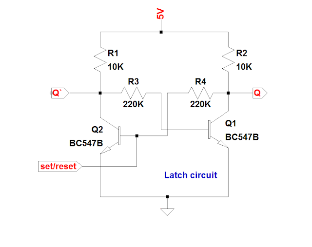
The circuit diagram is given below,
Circuit Explanation
Consider the above circuit, It is a practical working latch circuit. Here each transistor collector is connected to Vcc through a resistor. The resistor is used to limit the collector current of the transistor, otherwise the transistor will burnout due to the excessive current. The output is taken from each transistor collector point. If transistor is in ON then we obtain a logic '0' (Gnd) and if transistor is OFF then we obtain a logic '1' (Vcc) through the resistor. If we need more current in logic '1', then lower the collector resistor value. But there is a problem, the resistor is short circuited to GND when the transistor is ON. So there produce a wastage in power so the transistor get hot. Each transistor base is connected to the collector of the next transistor, it is for to obtain the feedback for trapping the data in it. The base resistor is used to limit the base current otherwise the transistor get damage. Data In and output are taken from the two different transistors.
Working
Assume that first the transistor 1(Q1) is at ON position. So output Q is at logic '0'. The transistor 2 base get a -ve voltage from transistor 1 collector through the resistor. So it is in OFF position. So, now we apply a +ve voltage forcefully to the transistor 2 base. So it is going to ON position. So now is at logic '0'. This -ve voltage Switch OFF the transistor 1 So we get a logic '1' at Q. So we successfully store data which is provided through the data in. The latch truth table is given below.
For it's making procedure, please visit my instructables page; link given below,
Thanks for viewing........


I f I want to use 2 Flip flops connected in series and the set/reset switch of one is connected to the input of another and the output of the other to the first one what would be changes I had to incorporate in the circuit and one more thing I want to operate this circuit in 12 v/9v. Any changes in the value of the resistors needed?
ReplyDelete
ReplyDeleteGood information.
----------------------------------------
I work in visit Stabilit America