 |
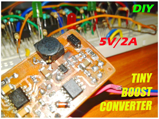
| Tiny boost converter circuit in one of my project |
I already made a Blog about boost converter. That is also a 5V one. Here I made a second 5V boost converter circuit by using another IC which is very small than the previous one and it only have 6 legs instead of 8 legs. I made it is for using it in my portable project. This boost converter need only very low external components and it is work at a higher frequency in the range of MHz. So the inductor size needed is low. It is capable of providing a current maximum of 2A to the load. For portable projects it is enough current. So considering the features it is very useful in portable projects. I am not explaining more about boost converter because once I explain well in the previous Blog. So visit it for more details about boost converter. Link is given. https://0creativeengineering0.blogspot.com/2019/04/5v-boost-converter.html
Circuit Diagram
 |
| 5V boost converter circuit diagram |
 The above circuit shows the circuit diagram. The IC used here is the MT3608. It is works at 1.2MHz frequency. So we need only small sized inductor (higher frequency need low value inductor so size reduced). The switching mosfet is also inbuilt in this IC. So we need only less number of external components. The 'EN' pin in the IC is the enable pin. A high voltage (Vin) enables the boost converter and a low voltage (GND) disables the boost converter. The resistors are used to give a feedback voltage to the IC for fixing the output voltage. Its value determine the output voltage. Here it is designed for getting a 5V output. The design equation is given here. The LED is used to indicate the presence of output voltage. This is the necessary details about the circuit. If you like to know more about the IC. Visit its datasheet.
I use this circuit in many projects which I completed. The above image is from one of my project.
I believe that this is useful for you...
Thanks for visit my Blog. See you again....
For more interesting projects visit my YouTube, Instructables pages.
Awesome article! Thank you! Is there a reason you used 2, 150k resistors in parallel instead of a 75k and 2, 20k's instead of a 10k? Also, would a XAL6060-333MEC be a good choice for an inductor if I expect between 1 and 1.5 amps load? Your help is much appreciated.
ReplyDeleteThanks for sharing this! Discover the power of Teenyfy, the ultimate Short Link Converter. Simplify your URLs, boost clicks, and track analytics with ease. Perfect for businesses and marketers looking to optimize their online presence and maximize engagement. Try Teenyfy today!
ReplyDeletehttps://www.teenyfy.com/
This converter is ideal for portable projects due to its minimal need for external components and its operation at a high frequency of 1.2MHz, which allows the use of a smaller inductor size. The MT3608 can provide a maximum current of 2A, sufficient for most portable applications. Highlights include an integrated switching MOSFET and an enable pin (EN) for converter control. Detailed information on step-up converters has been covered previously, and this compact and efficient design is very beneficial for various portable projects, with a schematic diagram that makes it easy to understand the circuit. Additionally, incorporating Stabilit America FRP panels in the project can further enhance durability and performance.
ReplyDeleteVery great post. Thanks for sharing this post. Great article on DC-DC converters! They truly are essential for efficient power management in various electronic applications. I’ve had the pleasure of sourcing High Quality DC - DC Converters from Tomson Electronics, and their products consistently deliver excellent performance and reliability. For anyone looking to purchase or learn more about these converters, I highly recommend checking out Tomson Electronics for their comprehensive selection and knowledgeable support team. They offer a range of options suitable for different needs, ensuring you get exactly what you require for your projects. Keep up the great work with these informative posts!
ReplyDelete