 |
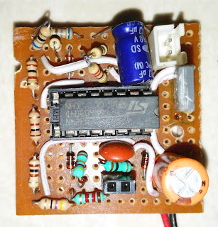
| Completed Auto fan speed controller PCB |
It is an automatic 12V DC fan speed controller for using in different electronic equipment like power amplifier for cooling. The fan speed is controlled based on the temperature. The temperature is detected by using a thermistor. Thermistor is a passive sensor. Its resistance is varied based on the temperature. It is two types -ve and +ve type. In -ve type the resistance is decreases for increasing the temperature and for the +ve type the resistance is increases with the increasing temperature. Here the speed is controlling in 4 steps. I design it to use in my power amplifier to remove the heat from the heat-sink very quickly. By using this fan I reduce the heat sink size. So, it is a very efficient and intelligent circuit for equipment cooling.
Circuit Diagram
The circuit diagram is given below.
 |
| Auto fan speed controller circuit diagram |
Here the circuit is work based on the op-amp IC LM324. It is a quad op-amp IC. Here it is wired as comparactor for comparing the input voltages. That is we detect the temperature by comparing the voltage. The thermistor (-ve type) is connected as a potential divider thus its voltage is varied with respect to the temperature variation. Here a stable reference voltage is provided by the 9.2V zener diode circuit. The diode reference is connected to the inverting input via different potential divider to create different voltages at each comparactor input. Thus by this arrangement we compare the thermistor voltage in 4 different stages. The required output is the -ve output voltage. The -ve is get when the op-amp inverting terminal voltage is greater than the non-inverting voltage. The diodes are used to prevent the +ve voltages from op-amp otherwise the op-amp output will short circuited. The each output is connected to a common transistor via different resistors. The resistors are used to limit the base current. The 390K base resistor is used to avoid false ON of the transistor. The 3 capacitors are used to stabilize the voltages at the capacitor connected points. This is the circuit explanation.
Working
The images in the right side is the completed circuit in a common PCB. The thermistor used her is a -ve type. Thus at room temperatue the resistance is very high so the potential divider voltage near Vcc (12V). The reference voltage 9.2V is dived into different sub voltages and each connected to each op-amp and the higher voltage is to the top op-amp and lower is at bottom op-amp. So at room temperature all op-amps non-inverting terminal voltage is higher than the inverting terminal. Thus the transistor base is at high. Thus the fan is OFF. When the temperature is increasing, the thermistor diver voltage decreases. At a point the top op-amp non-inverting voltage drops below its inverting voltage. So it produce a -ve output and the transistor get ON and thus the fan get ON. In further increasing the temperature all the op-amp activated one by one. At last all the op-amp activated and produce a maximum transistor base current and the fan get its maximum speed. This is the working of this circuit.
Making
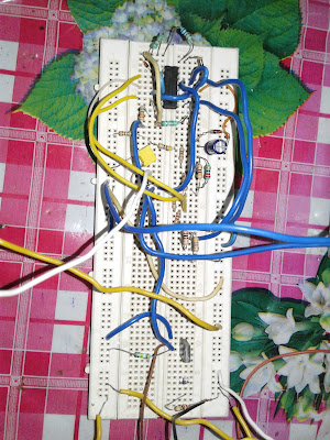
First I test the circuit in a bread board and then it is soldered into a common PCB (prototype PCB). You choose a good quality common PCB and soldered in it. Connect the thermistor eternally through wires to keep it in the highly heated position. Use precision resistor for proper working.
 |
| Circuit testing on a bread board |
If you like it. Please support me. Follow me to get new interesting projects instantly.
Thanks for viewing my BLOG.
Bye see you again...


Good information.
ReplyDelete-------------------------------------------------
I work in fiberglass roofing panels
A motor will not have an even magnetic field if an incorrect-sized capacitor is installed. This will cause the rotor to hesitate in uneven regions. can you use a larger run capacitor
ReplyDelete